SDC Left Hand Door Locking Device - Use With a Retiring Cam - 786-501-LH


SDC Left Hand Door Locking Device - Use With a Retiring Cam - 786-501-LH
Lead Time: Built Per Order 2-4 Weeks - Depending On Quantity - Note: We Cannot begin fabrication until a completed entrance data sheet is completed and returned to us for processing.
The SDC Door Locking Device installs on Double Swinging Elevator Freight Doors and is used with a retiring cam. This device has three contacts. One for door locked and two for door closed.
Models Available / Specifications
ITEM: 786-501-LH
250V AC, 2 Amps | Min. Travel: 7/8” | Force: 1.8 lbs. | Heavy Duty Cast Iron Enclosure, Latch and Roller Arm, Self Wiping Metal Loaded Contacts
Model Not Available
Please note that the design and construction of this interlock will not prevent water or dust from entering the enclosure. For wet, dusty environments like this we recommend using the hazardous location model as well as increasing your maintenance.
ITEM: 786-501-HS-LH
Hazardous Location Model - Class 1, Division 2 - Groups, A,B,C,D - Hermetically Sealed Contact Block Rated UL, CSA. Switch built to NEC Code requirements for Class 1, Division 2, Groups A,B,C & D Locations - (360VAC Inductive)
Items You May Need To Complete Your Installation
Device Description
Double Swinging Doors - SDC Interlock - Retiring Cam Required
The SDC is a true elevator door interlock retiring cam required device. It has three electrical contacts, two for each door and one center one for door locking. It must be used with a retiring cam and wired per the controller companies instruction. These contacts are wired in series together as part of the safety circuit. These contacts are made up when the doors are closed. The interlock mounts horizontally on the top center jamb where the doors meet. Each door has a locking bar assembly vertically mounted, consisting of a bar and a locking hook latch. When the door is closed the locking hook latch engages the door contact drive, mechanically latching the door, and closes that door contact. When both doors are closed and latched the elevator is set to run. When the roller assembly leaves the retiring cam the safety link rotates into the hook latch assembly on the active door preventing door opening while the car is in motion.
When the car stops at a floor, the retiring cam stationary cam pushes the roller assembly, unlatching the safety link and opening the center contact. This signals the controller that the door is unlocked. This allows the active door handle to turn and lift up the door keeper, allowing the door to open. The inactive door is opened by reaching in and pulling the inside door bar up allowing the door bar latch to exit the lock as the door opens.
When ordering specify hand. The hand is determined by standing inside the elevator looking out. The side on which the zone control is to be mounted (left or right) is the hand to be ordered.
These interlocks can be made with hermetically sealed contacts for Class 1, Division 2 (Hazardous Location) applications. Your order may have been built this way so make sure you follow the proper wiring guidelines according to the NEC code.
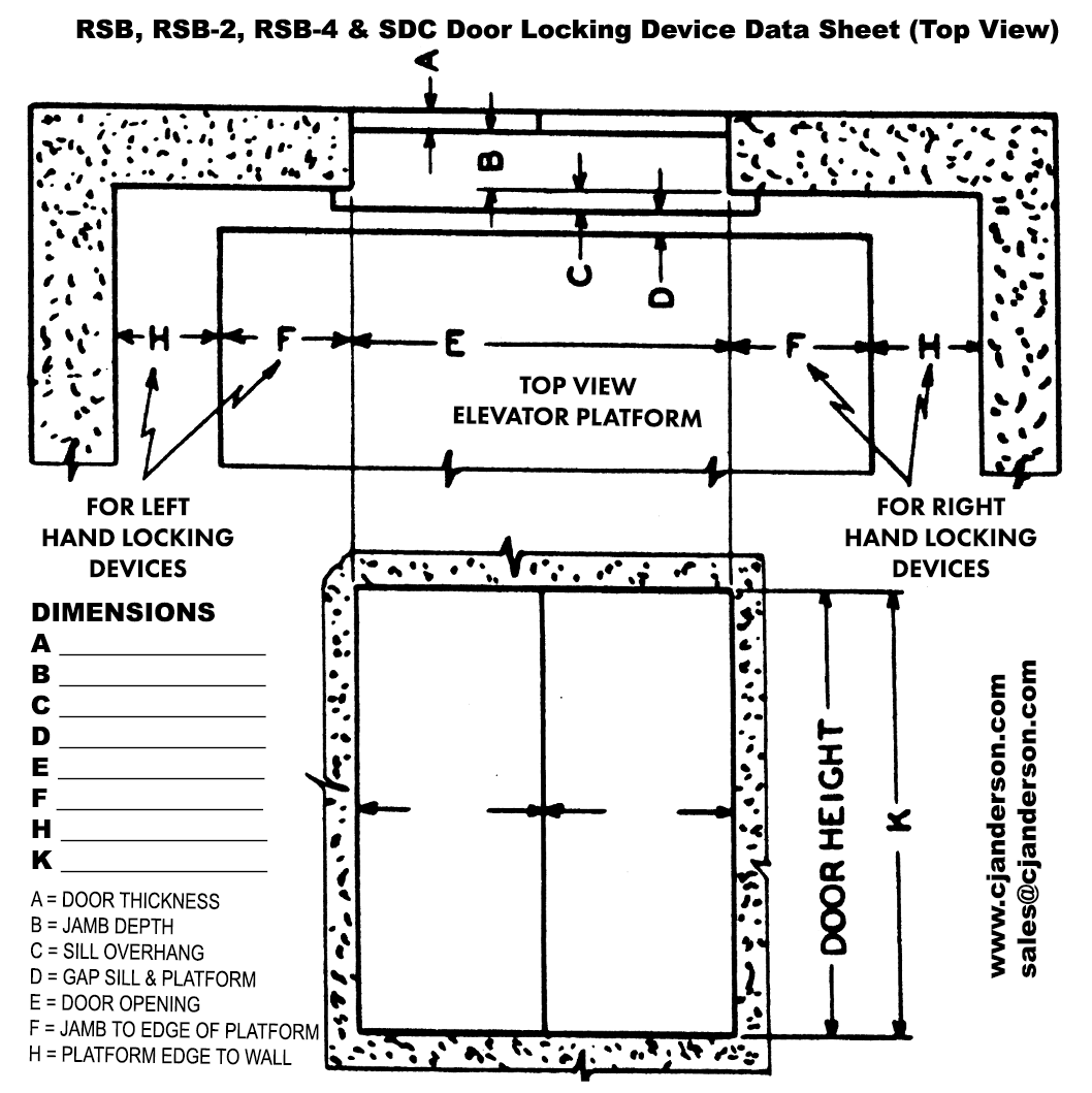
A data sheet showing door height, width, thickness, running clearance, corner offsets and depth of jamb must accompany the order.
You must fill out the information shown in this image above for each entrance for each locking device required. You can click and download a .pdf copy of this document below.
CJA - Door Locking Dimensional Datasheet Download.pdf
Features
• All Solid Cast Parts
• Heavy Duty Contacts
• 250 Volts AC or DC
• Self Wiping Contacts
Installation/Maintenance Guide
SDC Installation/Maintenance Instructions.pdf
Please email sales@cjanderson.com for assistance with any questions you might have.


